It is said that the growth of any nation is directly related to the percentage of Hams in it. Japan, the most Ham populated country in the world with 1 million Hams in it, according to a 1995 survey, is the living proof. I spent those most fruitful years of my life in Ham Radio – I enjoyed it. The basic driving force was certainly my passion for electronics. As I interacted more with this royal hobby, I learnt that there is discipline in it, patriotism in it, love for humanity and Nature in it and an unending quest for answers also are in it. It can be defined as a spare time hobby of people interested in radio communication techniques forming into an international network of friends and living committed to the growth of humanity and Science. It is an unending ‘ragchew’; it is experiments and innovation; it is polishing personality and growing more global; it is also relentless service of the society and the nation. As you switch on your rig, after acquiring proper license, you also will experience the discipline which all Hams follow, the respect with which each other behaves and the spirit of equality that prevails wherever Hams are.
In Part 1, I have given a brief account of Ham activities in the south, and a briefing on those first seven Ham Fests (all of which I attended in full). I think that without an idea on the community into which one intends to join, it will be hazardous to think of becoming a Ham. It is about the last quarter of the previous 20th century that I speak of.
Hams have a bright record of public service. Part 2 gives you a series of true stories, all intended to give the reader glimpses into those silent possibilities where a Ham perfectly fits in any society. In 1992, I wrote these stories in a Malayalam Science magazine, ‘Electronics for Everybody’. The entire texts are reproduced in Part 2 of this book, as it was.
It is an amateur who first used Short Wave, it is an amateur who came out with SSB and various modulation techniques. At a time when a 200 meters range Citizen Band Radio was sold for Rs. 12,000 or more in India, Amateurs developed Short Wave transmitters that cover the entire south India and more for Rs. 200/-. My enthusiasm to share my shack experiences with others was the motive behind the much appraised article series, ‘Gateway to Ham Radio’. Shri B Soman Nair, Chief Editor of the magazine, ‘Electronics for Everybody’ solemnly invited me to write in the magazine and in January 1995 the first chapter of Gateway to Ham Radio was published; it continued up to 1998. This book truly owes greatly to this great man – Shri. B Soman Nair.
Even after 18 years, I used to get mails requesting for a copy of it. But it took this much time for me to realize that it was a useful piece of sharing for budding Hams. All that I remember was that each article had consumed a minimum of 10 days to prepare it. There is no surprise if a man who has done his academic studies in English language and literature needed so long a time for even simple chapters. Part 3, which is the heart of this book, owes greatly to OM Jayachandran VU3 BWB (Ernakulam) and OM Madhu A65DE, from Vaikom (Kerala). Unless they had made the old magazine copies available, reproduction of the texts would not have been possible at all.
In Part 4, I have given the syllabus for ASOC Exams, Samples questions and Answers, formalities required for an exam and finally details of Amateur Radio License fee and its application formalities.
Thank you all my Guides, Masters and Friends who have helped me prepare this book. I do not believe that this is ever a befitting expression of my gratitude to Ham Radio, for all that I have received from it; this is only a squirrels share. I dedicate this book to all those First Generation Senior Hams, who could build this hobby into a way of life for all who have concern for oneself and the society in which we live.
Thank you
Joseph Mattappally
Part 1 - My SWL Days
 It all began in 1982, in which I happened to read a Sunday Supplement exposure (Malayala Manorama – Malayalam Daily) on Amateur Radio, written by one James Kalassery. He had written that Ham Radio is the most royal of all hobbies and it is a network of licensed Amateurs from around the world, which hasn’t any restrictions of age, gender, caste, creed or social status. At that time, I was only 30 and was managing a electronic equipment’s servicing and spare parts selling shop in my nearest town – Ponkunnam. I contacted OM James Kalassery VU2 ARL (Kochi), the writer, from whom I got the initial guidelines (OM, means ‘Old Man’ and it is how Hams address all licensees). KARL (Kerala Amateur Radio League), founded by James, based at Kochi was the first Ham’s Club that I joined. The first Ham event I attended was the Second All India Amateur Radio Conference organized at Kochi. Amateur Radio Society of India (ARSI) and Federation of Amateur Radio Societies in India (FARSI) were the National level organizations of Hams at that time. They later merged into one (ARSI) and continue to be the only society in India approved by IARU. The memento I got during the ‘82 Kochi Conference is still in my keep. Though the Conference was packed with senior celebrities from around India, it was more or less an assembly of strangers for me – I was not even a good listener at that time. But I still remember blind Om Chakravarthy (VU2TTC) from Tamil Nadu; I still remember the enthusiasm with which those celebrities hugged each other; I sill remember the stall demonstrating microprocessors; I still remember the Eyeball QSO contest held there.
Om Abraham VU2 AHM, 25 kms. away at Pala, was my nearest Ham. Others in the district were a few committed experts - OM Dr VK Kuriakose (VU2 VKK), OM TG Guhan Menon (VU2 TG) and Om DR PP Kurian (VU2 PP). I got all sorts of helps from all these fore runners in this district. I got my 2nd grade license in 1984 and my first grade in 1986. When I got my grade 2, the total no. Hams in Kerala was below 150. By that time there emerged a batch of 2nd generation active Hams, all of who were mostly home brewers. A lot of circuits were shared at that time. Taking lavishly from all these concepts and adding more from OM Guhan, I too developed a 12 V - 5 W - 40M transmitter in 1990 with a D882 transistor in the final. It cost hardly Rs. 1000/-, even when it was set in a beautiful cabinet.
My interaction with HRG (Ham Radio Guild) founded by OM Mukund (VU2DRL) helped me to explore Ham Radio further and most of my field experiences like Popular Car Ralley, Operation pilgrimage at Sabarimala and Velankanni, Field Days, QSL Beareau service, Emergency traffics, Trans India Contest, events like Wireless ’91, JOTAs (Jamboree on the Air) owe to HRG.
Almost until 1990, every year, Amateur Radio Clubs all around used to organize yearly get togethers in which people from various places assembled for eyeball QSOs (meeting persons face to face). There were exhibitions, technical talks and Rig experiments. One thing I noticed – each Club behaved more or less like a dissident from the main stream. Though home brewing is the backbone spirit of Amateur Radio, most of the high profile Clubs and conventions were hanging around Commercial Equipment and hi-tech discourses. Not much space was allotted to QRP home brewers.
The Story of Ham Fests in India
Revisiting the growth of Ham Radio in Kerala, will definitely help the readers to understand the features of this hobby better. Almost all the Clubs in Kerala took shape in or after 1980. The Nanthancode Electronics Club (Trivandrum), which organized the first ASOC exam in Kerala, was the first Hams Club in the State; OM Hari VU2 BY from Kozhikode was the first Ham in the State. As years passed by, a heavy flow of enthusiasts filled the country. A good number of Parliamentarians also were Hams at that time, may be thanks to our former Prime Minister, Om Rajiv Gandhi (VU2 RG). As a result, more local Hams Associations took shape and home brewing also grew intensely. It was a time in which ASOC exams were held on a regular basis all over the South. Early Clubs, as I understood their activities, were trying to outshine another, even though none of them used the word competition. They did not fundamentally promote home brewing but basically continued to be a creamy layer, with enough grains in it.
It was at such a scenario that a few Hams – OM Sharma VU2LV, OM Natan VU2 KGN and OM Dr Jayakumar VU2JKR convened a meeting of Kerala Hams at Nithya Hotel, Kottayam, in 1991. The purpose was a new Association beyond the existing Club holdings. The organizers assumed that even KARL, the only state wise Hams association of the times, does not function up to everybody’s expectations. But the participants took this chance to share their views on these warring Amateur Radio Associations and the difficulties home brewers face. Everybody agreed to the point that inter-club relations should be improved highly and home brewing should be promoted much more. The meeting unanimously agreed to appoint a three members ‘Kerala Amateur Radio Clubs Coordination Committee’, in which Om Joseph VU2JLX, OM Jose VU2 JKV and myself were members.
The first thing that the committee decided do was to work for the promotion of home brewers thus bringing them all under one umbrella. The new Committee found that intensive efforts are necessary to do this. That was the prime reason behind launching of Ham Information Net (Hinet), which the committee initiated on 40 meters. This happened in August 1991. It began functioning on 7065 Khz. between 8 AM and 8.30 AM on all Sundays without break. Joseph (VU2JLX) and myself (both home brewers) were controlling the net regularly. Gradually it paved way to Radio Round Tables, exclusive discussions on pre selected topics, headed by experienced Hams and some times scripted and sponsored by Ham Clubs. Radio Round Tables timing was 7.15 AM on Hinet frequency, on Sundays. On some occasions it continued even after Hinet. Within a short span, Hinet became the centre of South Indian home brewing activities and the first gateway to SWLs. Gradually, on-the-air special classes were organized on various home brewing strategies under well experienced senior Hams. The focus of the co-ordination committee happened to be the promotion of budding hams at the lower layer.
Slowly, the committee found that on-the-air audio demonstrations are not enough. Many people needed live demonstrations. We never wanted to leave anybody astray – a field day was planned. Field days, as such, were mostly limited to eyeballs, a few antenna/propagation experiments, local food service experiences and chats. They were more or less study picnics. No, that was not what we were thinking of. We definitely wanted more time to share shack techniques like PCB designing, etching, drilling, soldering, coil winding, rectifier assembling, modulation transformer winding, mounting ICs and transistors, SWR matching, frequency counter assembling, antenna designing, receivers, BFOs Oscillators, operational etiquettes and much more…. After prolonged discussions, we decided to make this a two days event. I was authorized to coordinate the event – a Home brewer’s workshop. The whole Hinet family took the idea seriously. Discussions went on for a befitting name for this event. Home brewer’s Meet, Hams’ Festival, a lot of proposals were discussed. The title ‘Ham’s Festival’ was finally approved but as the event closed in, the name became Hamfest.
One of our decisions we eventually made in this regard was that the merits of this event should not be attributed to any single person, and all the way a common spirit was maintained and it is this energy of unity that paved the way for Hamfest India later. Money was the main villain. Our concept was to render the support free or at the maximum at actual food and accommodation expenses. One name I wish to remember at this time is that of who came forward offering their support. Thanks to Mukund (VU2DRL), then secretary of Ham Radio Guild, Kochi, all participants were free to pay only an amount of their pleasure and Ham Radio Guild filled the deficit amount needed. It was they who brought the nametags printed, ‘Hamfest ‘91’ which was the only material on which the event name was printed.
Hamfest ‘91
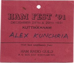 The first Hamfest began with a welcome session in Pius 10th Higher Secondary School, Kuttikanam on……. It was Om Menon VU2MAH from Quilon, the oldest Ham present there, who presided the first Session. After initial formalities, all moved to the Gov.t Guest House at Kuttikanam, a hill top tourist centre in Idukki dist. on Kottayam - Kumali Highway on the Eastern Hill ranges. The whole team as planned before split into various stalls/groups, some demonstrating home brewing techniques, some selling kits and some holding question answer sessions. Senior experienced Hams like Om Gopi VU2 EGM, OM Ravi VU2 RDN, Mukund VU2RDL lead the sessions.
All the participants irrespective of status, ate together, slept together and thought together. It was an unforgettable experience. During the closing session, none could hold their appreciation for the event. It was simple, elegant and well organized, where Hams came and joined on their individual standing, irrespective of their club or society bindings and collectively worked in the true spirit of the hobby. Hamfest ’91 was a grand success! Everybody wanted this event to continue every year, in the same spirit of togetherness. In the final get together, Om Gopi VU2 EGM was unanimously appointed Gen. Convener for Hamfest 1992.
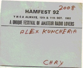
Hamfest ‘92
I kept my promise to Om Gopi and worked for the event as Programmes Coordinator. Hamfest ’92 was a whole year event for the various committees and members working for it. It was organized at Alwaye on October 10th and 11th. Reception and registrants service was managed by a committee under Ravi (VU2RDN), Food and accommodation was managed by a committee headed by Joseph VU2 JLX, Souvenir Committee was headed by Mukund (VU2DRL) and Awards committee was headed by Sadhujan (VU2PGS). The registration fee for SWLs were just Rs. 25/-. From 1992 on, special event call signs were allotted to the event and train travel concessions also were made available to the delegates.
In he General Body meeting held, OM Premchand VU2RPC from Tamil Nadu was appointed Gen. Convenor for the upcoming Hamfest and the hosting Club for HF ’93 became Kovilpatti Amateur Radio Club. Our dream of shaping Hamfest into a South Indian event, thus became came true.
Hamfest 93
 The state of TN, then the most Ham populated State in India took it as a challenge. Om Madhu VU2MUD from Mysore already had agreed to host the 1994 Hamfest. Live demonstration stalls, elaborate flee/junk market, assembled/important equipment /sales display stalls, presence of celebrities, awarding commendable contributions, prizes to contest winners…… everything went on among wide applause. During Hamfest ’93, I also received an exclusive presentation – Ham of the Year for 1992 Award declared by Ham Radio Guild, which included – a citation and a cash of Rs. 5000/-. As was previously arranged, the Mysore Hams came forward to host Hamfest ’94 in Mysore.
Hamfest ‘94
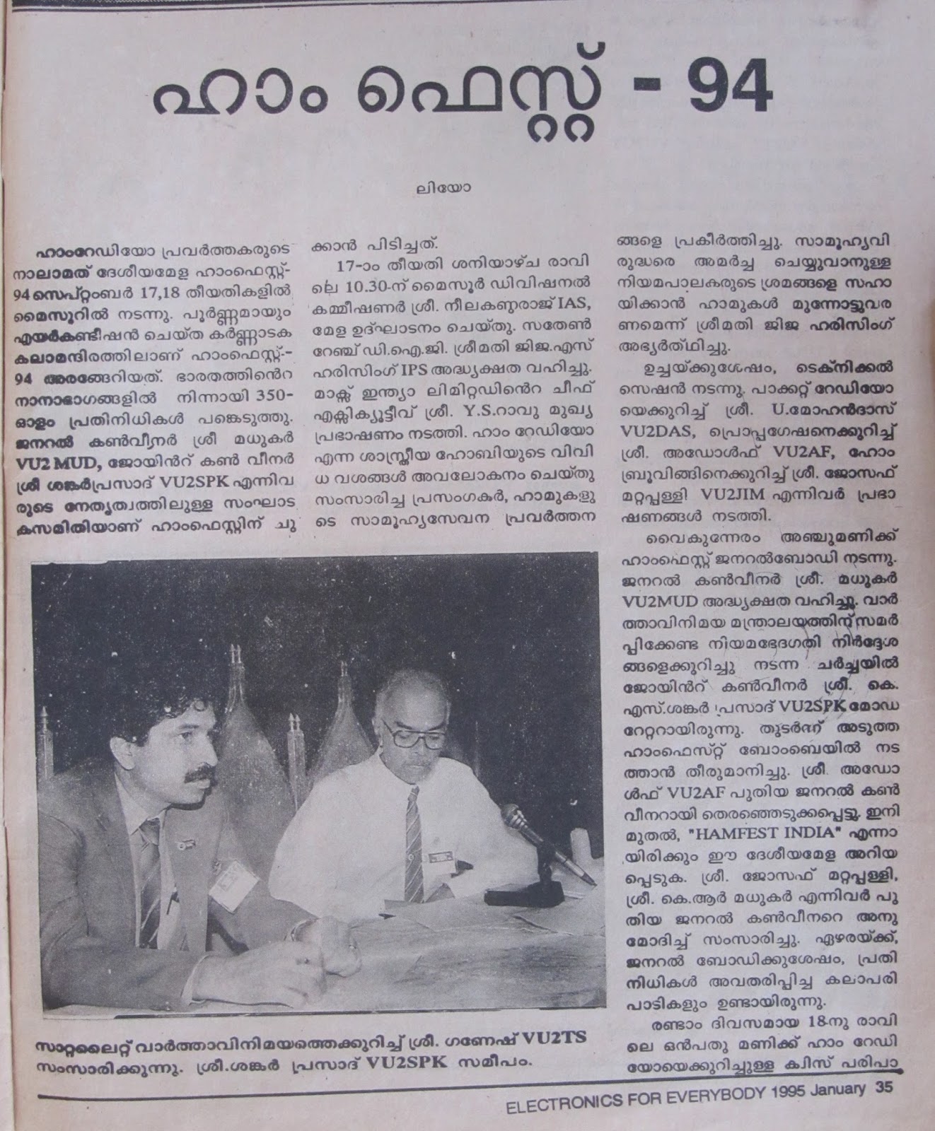
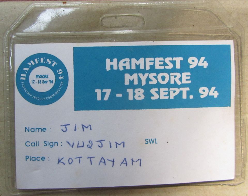
According to a media report on Hamfest ’94, the fourth South Indian Ham event, it was celebrated in a fully air conditioned auditorium - Karnataka Kalamandir, Mysore - on 17th and 18th of September 1994. From around the nation, some 350 Amateurs attended the event. The event was organized by a team headed by Om Madhukar VU2MUD (Gen. Convenor) and OM Shankar Prasad VU2 PSK (joint Convener). The fest was inaugurated by Shri Nilkandaraj IAS, Mysore Divisional Commissioner, at 10.30 AM on 17th. The inaugural meeting was presided by Mrs Jija S Harisingh IPS, Southern Range DIG of Police. The Keynote address was delivered by Shri YS Rao CEO of Max India Ltd. The dignitaries who addressed the delegates appreciated those distinct features of Ham Radio and Mrs Jija requested Hams to come forward in support of the Police force in suppressing anti social uprisings/elements.

Hamfest ‘95
Hamfest ’95 in Mumbai was a milestone in the growth of Hamfests. The three days Prefests in all the 4 Zones in India was an added attraction. OM Ponnuswai VU2 APS was in charge of the South Zone and he organized a 3 days workshop in Erode on 25th, 26th and 27th of August 1995 with the slogan, ‘Equip all Shacks’. HFI ’95 was kicked off with the King City contests in September. Here is the full translation of a media news coverage.

‘The National Festival of Hams in India, Hamfest India ’95 was appropriately celebrated in Tejpal Auditorium in Central Mumbai on 28th and 29th of December 1995. It was this auditorium that witnessed historical events like formation of Indian National Congress and declaration of Quit India Movement. This event was the biggest gathering of Hams in India – it had more than 1000 registrants, including those from Dx. HFI ’95 programmes were streamed live through TV and Radio. Other media also reported it with due importance. It was attended by International Telecommunication Union (ITU) representatives and Gov.t of India officials like Shri. Vittal IAS. Around 15 sub-committees were working behind HFI’95. Elaborate stalls of States and worldwide equipment/components manufacturers were all reserved for the event. The best home brewer award of Rs. 50,000/- and the Man of the Fest award for the winner of the on the spot quiz contest, all were added attractions of Hamfest India ‘95.
Rich talks on various aspects of Ham Radio definitely took the delegates in awe. In the Gen. Body held in the evening, the delegates talked on the difficulties Hams face with regard to Gov.t support. Shri P K Gulatthi, Wireless Advisor to Govt. of India assured the delegates to avoid unnecessary delay in issue of licenses and reduce import formalities on Ham equipment.
It was quite unanimously that the delegates appointed OM Avinash Mihshra VU2 EM as Gen. Convenor for HFI 96, the venue of which was declared to be Kolkata. Among wide applause, OM Joseph Mattappally VU2JIM invited him to the dais in the traditional style and spoke congratulating the new Gen. Convener. Replying to the felicitations OM Mishra promised that the next Hamfest also would be giving priority to Homebrew spectrum. Awards and certificates were presented on the second day afternoon. Shri Sargath Sing, ITU representative presented the awards. In the King City contest five out of nine prizes were bagged by Kerala and the hero was OM Sunil VU2UKR. A memorable programme of the event was passing the ITU flag to ARSI in honour of the commendable services they have rendered to Ham Radio. OM Mishra, who had already taken charge of the dais, appreciated OM Adolph for the beautiful performance, team HFI ‘95 presented in Mumbai and that quite perfectly. As a mark of gratitude OM Mishra presented him a beautiful bouquet. Passing the official flag of Hamfest India was the last ceremony of the day. Before the fest was called off, all the delegates stood hand in hand and repeated the community pledge. The organizers also had issued a special souvenir and All India Hams Telephone Directory.
Hamfest India ‘96

Adding another colourful feather on the cap of Hamdom, HFI ’96 was elaborately celebrated in Salt Lake stadium Kolkata, on 19th 20th and 21st of December 1996. Of all the Hamfests this event was different with the highest no. of Dx delegates ever. The entire 500 beds dormitory there was full with Hams and SWLs from across India. Registration fee for Hams was Rs. 500 and for SWLs it was Rs.200. It included charges for food too. There also was a total no. of around 900 registrants. Look at the media report: Inaugurating the event, which the Kolkata media covered in full, ‘Prof. Divakar Ven, Director of the Acharya Jagadish Chandra Bose Institute, detailed the past 100 years of Radio and innovations with it. The whole event was dedicated to late pride of India, Acharya Jagadish Chandra Bose. There were very informative and nourishing talks on different topics, Joy City contests, cultural programmes of Doordarshan artists, exhibitions, conducted tours, sales stalls (Dx and VU), commercial equipment display, mementoes distribution etc. Everything added together, HFI ’96 was one of the major events organized in W. Bengal. The Gen. Body there discussed in detail prevailing problems that Hams in India face. The Gen. Body decided to appoint a committee to see into it and work for a satisfactory remedy. It was because of the joint effort and call of Kerala Hams, Kerala got a 3rd chance to host the event. HFI ’97 was decided at Kochi. Among wide applause, OM Joseph Mattappally, on behalf of Kerala Hams, received the official documents and HFI Flag from OM Avinash Mishra. In his brief thanks giving address, OM Joseph Mattappally appreciated the arrangements done in Kolkotta and congratulated the organizing committee for the tremendous effort they put in it.’
The days were unforgettable for me too. At Kolkata, I could meet St. Mother Teresa, alive. She was so weak when I saw her. Still I remember that the sisters there got two signed mementos for me. She passed away within a year.
Hamfest ‘97
The first thing OM Suresh, the Gene. Convener, did was appointing a 101 members volunteers team and a dozen of expert committees, intended to manage different activities. Radio pilgrimage was a unique event in connection with the Kochi Hamfest. Five days prior to the Fest days, were reserved for tour packages for delegates from outside the state. Important activities proposed in the event were presentation of important technical papers, training in assembling of small gadgets like VFOs, QRPs, demo.s on Packet/Pactor reception, Internet usage information, exhibition and sale of old and new components/equipment, display and sale of books and gadgets, Radio pilgrimage, contest for prestigious JC Bose award and so on.

Here is the media report on HFI’97: ‘The 7th National meeting of Amateurs in electronics was celebrated in Renewal Centre Kochi on December 20th and 21st, 1997. There were technical workshops, seminars, group discussions, sale stalls, junk market, periodicals display, live demos on digital communication and changing amateur radio strategies etc. Internet booth was an added attraction. On the first day the functions started as OM Avinash Mishra VU2 EM hoisted the flag. OM Narayan VU2 NYR delivered the Welcome Speech and Ganesh VU2TS gave the Presidential Address. Shri V J Pappu, Pro-Vice Chancellor of Kochin University, was the Chief Guest who lighted the lamp and did the inaugural address. The souvenir was released by OM Saharuddin VU2SDN and OM Suresh VU2 SUO delivered vote of thanks.
At 11’ O clock OM Saad Ali and at 12’O Clock OM Saharuddin talked on VHF activities. At 3’O Clock OM George VU2 GT talked on Homebrewing VHF Antennas. At 4.45 PM OM Jayaram VU2 JN talked on homebrewing QROs. At 5.30 PM the General Body was called and it decided the next Hamfest Venue to be Bangalore and the Gen. Convener to be RCR Chandru VU2 RCR. From 9 PM onwards on the first day, entertainment Programs by ‘Waves’ Trichur added to the glamour of the event.
The second day began with ARSI Gen. Body Meeting at 8.30 AM. At 10’O Clock, Ganesh VU2 TS talked on Satellite Communication and at 11.30 OM Adolf anchored an on the spot Quiz competition, in which OM Madhukar VU2MUD won. At 12.30 OM AO Guntu Rao talked on modifying BEL transceivers. At 2’O Clock Ham Radio Guild distributed Trans-India Contest Awards. In the closing meeting OM Suresh VU2 SUO, Gen Convener, spoke to the delegates and he appreciated the grandeur of support he received from fellow Amateurs. Last item of the event was distribution of Queen city contest Awards and Certificates of Honour to distinguished promoters of the hobby.
 It all began in 1982, in which I happened to read a Sunday Supplement exposure (Malayala Manorama – Malayalam Daily) on Amateur Radio, written by one James Kalassery. He had written that Ham Radio is the most royal of all hobbies and it is a network of licensed Amateurs from around the world, which hasn’t any restrictions of age, gender, caste, creed or social status. At that time, I was only 30 and was managing a electronic equipment’s servicing and spare parts selling shop in my nearest town – Ponkunnam. I contacted OM James Kalassery VU2 ARL (Kochi), the writer, from whom I got the initial guidelines (OM, means ‘Old Man’ and it is how Hams address all licensees). KARL (Kerala Amateur Radio League), founded by James, based at Kochi was the first Ham’s Club that I joined. The first Ham event I attended was the Second All India Amateur Radio Conference organized at Kochi. Amateur Radio Society of India (ARSI) and Federation of Amateur Radio Societies in India (FARSI) were the National level organizations of Hams at that time. They later merged into one (ARSI) and continue to be the only society in India approved by IARU. The memento I got during the ‘82 Kochi Conference is still in my keep. Though the Conference was packed with senior celebrities from around India, it was more or less an assembly of strangers for me – I was not even a good listener at that time. But I still remember blind Om Chakravarthy (VU2TTC) from Tamil Nadu; I still remember the enthusiasm with which those celebrities hugged each other; I sill remember the stall demonstrating microprocessors; I still remember the Eyeball QSO contest held there.
 The state of TN, then the most Ham populated State in India took it as a challenge. Om Madhu VU2MUD from Mysore already had agreed to host the 1994 Hamfest. Live demonstration stalls, elaborate flee/junk market, assembled/important equipment /sales display stalls, presence of celebrities, awarding commendable contributions, prizes to contest winners…… everything went on among wide applause.
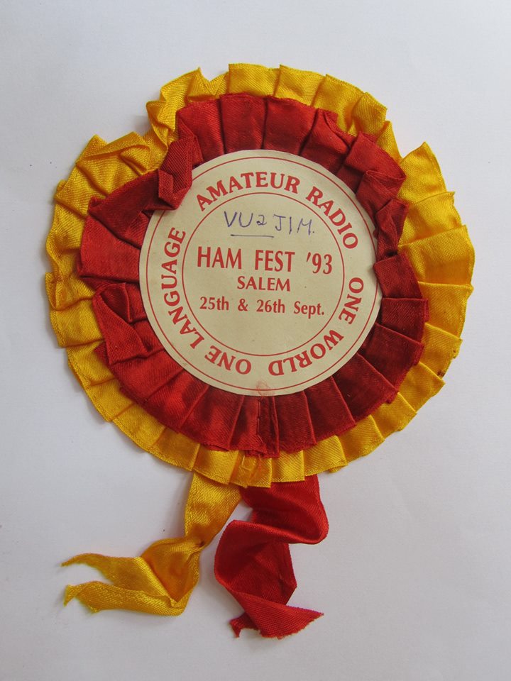


