
Electronics is the study of electrical energy in its numerous functional possibilities. Today, electronic gadgets are widely assembled by even small school students. Electronics, has now become the most talked about branch of Science and it is deciding our daily lives through numerous thrilling possibilities.
It is an SWL that becomes a Ham. Most of the operational ethics are learnt through patient listening only. Listening also helps a SWL to know who is who. In the last chapter, we discussed about modulation and the necessity of Oscillators in listening. For proper listening of all Ham transmissions we need at least a BFO. BFOs are not available for purchase. This we have to make for ourselves. It is important that one knows how to make a PC board for himself/herself. Bread Boards with holes and prints in definite patterns worked with more jumpers than components have its own draw backs. To be frank, minimum knowledge of the components, soldering expertise and a multimeter aside are not enough to work in a shack.
 Now take a graph paper at the actual size of the P C Board. Components should be mounted in a way that the leads do not touch each other. The second stage is preparing the layout. The size of the print is decided mostly depending upon the current the print line handles. In high frequency circuits distance between prints also are important.
Simple circuits are done on leg strips mounted on hard boards or assembled on multi purpose breadboards. But making own Printed Circuit (PC) board is not as difficult as many assume it to be. If a print layout is prepared it can be screen printed on the epoxy board and PC boards of commercial finish are possible. Before we proceed discussing many practical circuits let us learn the nuances of making a PC Board for ourselves.
The very first thing to do is drawing neatly, the circuit you propose to give life to. Further, decide the size of the board necessary to mount all the components. It is better to collect the components in advance. This will help us to know the size of the space each component requires on the board. Also we need to confirm lead peculiarities of the components and the mode of mounting the components - sleeping or standing. See fig's C-0/1A and C-0/1B
 Now take a graph paper at the actual size of the P C Board. Components should be mounted in a way that the leads do not touch each other. The second stage is preparing the layout. The size of the print is decided mostly depending upon the current the print line handles. In high frequency circuits distance between prints also are important.
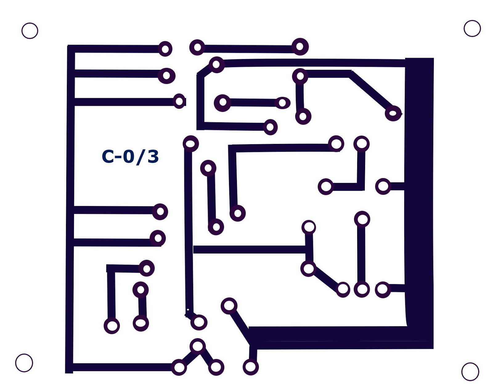
Now, make holes on the graph paper so that the leads come out at the graph side of the paper and mark the points. Assuming that the graph side is the print side in the PC Board, connect the leads with lines respectively as seen in the diagram. Lines should be straight and without bends and each should have enough space in between. In case crossing is required (unavoidable) draw the lines with a plan to connect the lines with a jumper wire at the mounting side of the Board. Next we we will take the copper clad board at the necessary size. Copper clad boards are available in different qualities. Most common are paper epoxy and glass epoxy both in single side and double side foils. If for most of the circuits, ordinary copper clad is enough in high frequency circuits, quality glass epoxy boards are needed. These boards are cut like glass breaking after putting groves on it with sharp knives on either sides. Hacksaw blade also can be used.
Screen printing technology can be used for printed boards with a commercial look.


How to draw a circuit for etching
If you find copper sulphate anywhere on the print side of the PC board, it should be cleaned with a dried cloth at press massage. Now the board is ready for having holes on it. In general cases what we require are 1mm and .8mm drill holes. Bigger holes spoil more lead, while soldering. Before beginning to mount components on it be sure that you have put fixing screw holes also on its' corners. Copper open to atmosphere may get subjected to natural corrosion. To protect it from similar damages and staining coat it with a paste of rosin crystals (available in hardware stores) diluted in some thinner.
While fixing the board on the chassis, use plastic beads to keep it a little high.

No comments:
Post a Comment