
It is very easy to assemble a RF Oscillator gadget but very difficult to tune it to the desired quality levels. Oscillator circuits can't be so swimmingly handled like an Audio Frequency amplifier. There are mainly two types of RF Oscillators - Hartley and Colpitts.

Hartley Style Oscillators (Fig: C-7/1A) working on inductive feedback have less starting problems but high stability issues. This is the first reason why more people follow Colpitts style which depends upon capacitive feed back principles. In Colpitts, just like in Hartley, there are parallel tuned (C-7/1B) and series tuned (C-7/1C) circuits.


To keep the 'Q' factor of a tuned circuit within the desired specifications, every frequency truly requires a different value of inductance in the circuit. To get the circuit resonating to a desired frequency at an intended inductance value we have chosen, the capacitive reactance (Xc) of the capacitor used in the circuit should be equal to the inductive reactance (Xl) applied in the circuit.
Core is an inseparable part of any coil. Since Air itself is a type of core, there is nothing called core less coil. At a definite inductance value, the number of turns in a coil vary in tune with the type of core used - the more number of turns the more will be the inter-turns capacitance in a coil. Type of core used for a coil is generally chosen with an eye on the frequency the coil is supposed to handle. The resistance the core applies to the Radio Frequency also is determining here. Having equal measurements at winding length and diameter is stability improving factor in RF circuits. Heat sensitive cores easily change the inductance of the coil.
Even though toroids and IFT type coils are used in 80 and 160 meters, on 7 MHz and beyond, air core coils wound on porcelain formers are recommended. When a RF coil is used in a circuit, especially a VFO circuit, they are to be mounted on the board at least a diameter away from the cabinet sides and active components; neither turns nor the coil as whole shall vibrate even a bit. This is why coils are found sealed with insulating varnish or special wax. The size of the winding wire is decided, only after considering the skin effect properties of the wire at the intended frequency.
Capacitors used in tuned circuits also should have specific qualities of low tolerance and high performance. Not only silver mica and polystyrene capacitors but also disc and Styroflex capacitors from quality manufacturers like Philips work satisfactorily. RF heating which results in frequency drifts is a common problem that affects the stability of an RF circuit. One way out is using more no. of capacitors - in series or parallel making the effective value used in the circuit at a recommended point (see fig.C-7/2). Actual recommended values are given in brackets.
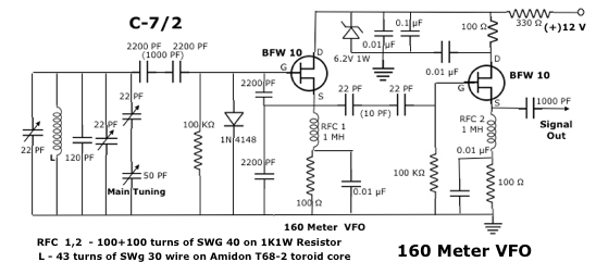
In fig. C-7/2, see a 1N 4148 diode used at the gate of the oscillator transistor BFW 10. Other than keeping the positive swing of the oscillating sine wave down at .7 V, it works as bias clamp too. As a result, the transconductance of the FET is controlled at positive halves of the signal, along with reducing higher changes in the junction resistance of the transistor. Just one diode like this is enough to reduce harmonic generation and stag stability also. 
Compared to bipolar transistors, FETs (Field Effect Transistors) have low noise level, higher dynamic range, satisfactory input - output isolation, higher input-output impdence and better stability, when used in RF oscillator stages. In a bipolar transistor if the out put Collector - Emitter current is decided by the current variation in the base circuit, in FETs, out put power is determined by the voltage variations in the input gate circuitry. This actually is the fundamental difference between a bipolar transistor and a FET. Among FETs the two popular types commonly used are Junction Field Effect Transistor (JFET) and Metal Oxide Field Effect Transistor (MOSFET). In MOSFETs not only that the elements, Gate, Source and Drain are separated with thin insulators inside it but also have a gate protector circuitry inside it, intended to safeguard the transistor from potential threat from static charges.
JFETs are more sensitive than MOSFETS and they are to be ver carefully handled especially while mounting or testing them. Do it disconnecting both the power supply leads connected to the board on which it is mounted. Another precautionary method is that it should not be tested with a meter operating at more than three voltage. Disconnecting soldering iron from the power socket when touching its' leads also is a precautionary step. MOSFETS do not require this high category care do not mean that they resist all sorts of pressures static or dynamic. There are many new generation ICs which also do not entertain a home desk treatment. Normally, FETs are mounted body close to the board and leads not unnecessarily exposed. Because FETs easily pick up AC hums, they are generally kept as away as possible from AC power supplies.
Much of the VFO based problems are caused by unstable power supply voltage. Either VFO power supply should be beautifully regulated or better work on battery itself. Even a slight fluctuation in power supply voltage might result in considerable frequency drift and FM traces. A 1W Zener diode used in the circuit is enough to settle this fluctuation issues.
Even if a VFO is assembled exactly according to the specifications of the designer, the RF voltage assured in the prototype need not be produced in the output. That is mostly because of the difference in the 'hfe' of the transistors used. In case the 'hfe' of the oscillator transistor is very high even if the tuning capacitor changed, a beat note might appear at a definite point on the radio. Increasing the value of the resistor between the Source and the ground is one solution for similar problems. This might affect the overall output strength of the signal. If the oscillator signal power is very low, there could be no signal at all in the out put. Therefore, this resistor value is decided by trial and error method and varies in each VFO.
 Out put RF voltage should not be increased beyond a point or decreased below a voltage, for best results. One suggested method is measuring the the Source voltage of the RF Oscillator Transistor using a RF Probe and follow a standard level in every circuit. Fig. C-7/3 is the circuit diagram of a simple RF Probe.
In tight coupling if maximum signal is transferred in loose coupling only a small part of the signal is fed into the following circuit. To avoid loading effect, signals are coupled only at definite power level. A buffer stage in between stages is not enough to completely avoid the impact of signal loading. Even if the oscillator transistors and the buffer transistors are the same, it may not reduce the loading effect but reducing the value of interstage coupling capacitor helps a lot.
There are some preliminary principles to be observed while assembling a steady VFO. The quality of the PC board used and the quality of printed lines, circuit design..... all are factors that decide the quality of the VFO signal. Glass Epoxy boards are always preferred for VFOs. Let print lines on the Circuit board be curved at places of 90 degree bents as generally seen. Working VFOs on battery voltage and keeping VFOs enclosed in aluminium boxes having a minimum of 18 gauge thickness are good measures to keep it steady and stable. In case the power supply is from an eliminator circuit, always use an RF choke and a decoupling capacitor at reception. Neither any part of the VFO including connecting wires shall vibrate at any condition nor it should have unnecessary switches on the box. A coaxial cable that matches with the out put impedance of the VFO is always better at the output.
 Wherever the receiving and transmitting frequencies in transceiver is different or if we prefer a split operation, receiver incremental tuning (RIT) is necessary. Even if both the frequencies are the same we know that at AM VFOs may have to be switched of and at CW slightly shifted away. RIT circuits, it there are, should also be fixed in the same VFO Box itself. See an RIT circuit in fig: C-7/4.
  Another reason why we preferably opt a RIT circuit is that mechanical switches adds to frequency shifts, depending upon the quality of contacts used in the switch. In fig: C-7/4A the circuit of a simple frequency shift circuit is given. Depending upon the value of the 22 pf capacitor used in the circuit the shifting value of the frequency also changes. RIT here is following the principles of a VCO here.It is natural that all home brewers ask for the simplest and low cost VFO circuit. It should be remembered that early home brewers were not ready to compromise at any quality deciding point. Gives below (C-7/5 ) a simple but most efficient 7 Mhz VFO circuit used by many.
The circuit of the stage RF amplifier given below (C-7/6) also is tested for quality and performance. This Crystal Tx also worked as beautifully as a low power Crystal Transistor.

L1 - 15 turns of SWG 24 on 3/4" PVC tube. RFC1 - 150 turns (SWG = 40) on 1KW 1W Resistor). Only if a beginner is familiar with more VFO circuits and other common related problems he will be able enough to manage problems that comes on the way.

No comments:
Post a Comment